About this course
Hello all and welcome to this yet another “arduino” course! And yes I am totally aware that there are more than a thousand of “arduino” courses out there, and some of them I have to say that are indeed very good. What I pretend to do with this course is to walk you (and myself, tbh) through the world of embedded systems, not just arduino. So eventhough I will start with the very basics of arduino such as general setup and using a lot of components like motors or sensors, the main goal is to follow that up with directly programming atmel like MCUs in C without even using Arduino as well as doing some more advanced projects such as designing own pcbs.
Pre requisites
I will start with the very basics of Arduino: Developing very simple projects, using arduino-processing instead of C and generally not caring a lot about analogue electronics. Said that I also assume that you have a solid understanding of the fundamentals of electronics, so you are familiar with the ohm law, know about basic components such as resistors, diodes and transistors and are able to design simple circuits.
Materials
I will post a full list of the requiered materials(component, cost and buying options) as soon as we advance enough in the course. In general terms you will need some arduino boards such as arduino unos, a bunch of resistors of different capacities, leds, buttons, potentiometers, protoboards, and a bunch of basic components such as ultrasound components, dht sensors, relays and such. Bonus points if you have an electronic tester, power supplies, signal generators and such. You can perfectly get all of the materials while you follow the tutorials, there is no need to rush.
Setting up the environment
Here we go! In this first tutorial we are going to install all of the requiered materials and we will learn the basics on how to operate with arduino. We will go straight to the point.
Arduino IDE
The first stage here is to get the Arduino ide. This software helps us writting “Arduino” code compiling it and uploading it to our arduino board of choice.
 support.content.office.net
Download the binaries “HERE” if you are on windows.
If you are on Linux (ubuntu and such) it will be easier to use the package manager
sudo apt-get install arduino
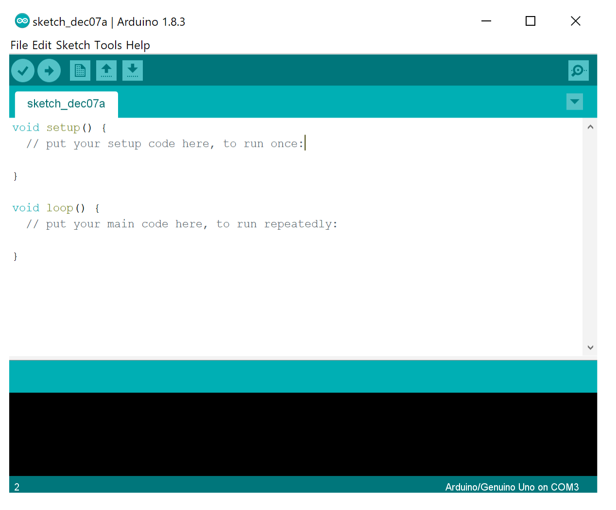
Once the ide is installed you should plug your board then go up on the “tools” menu and check out that your board appears on “port” and “board” submenus. There is no rocket science here, if your board does not appear you may have a specific problem related to the board or the pc.
Done that you should be able to write, compile and upload programs to your board.
Interacting with arduino in VirtualBox VM
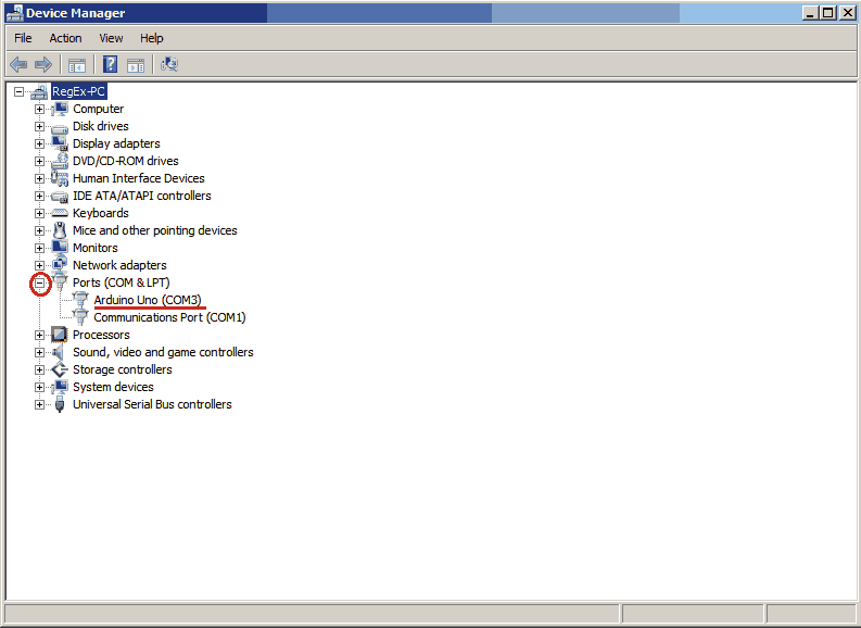
Probably some of you will try to run this on a virtualbox vm and rapidly find out that the arduino IDE does not detect any board even if “arduino X” is selected under the usb sharing menu of the vm. That is because all the communication related to code uploading and such is done via the serial port. So if you want to work on arduino on a virtualbox vm, you have to check what port is arduino using (device manager):
 http://joequery.me/
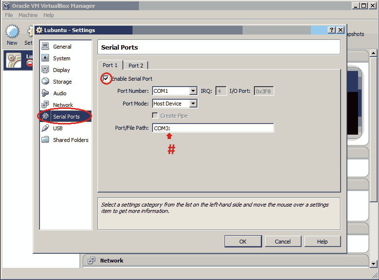
And then you have to add that port to the VM exactly like this :)
http://joequery.me/
And then you have to add that port to the VM exactly like this :)
 http://joequery.me/
Done that, you should be able to talk with an arduino box in a system running on a virtualbox vm.
http://joequery.me/
Done that, you should be able to talk with an arduino box in a system running on a virtualbox vm.
Manually uploading code to arduino
You may also want to work with your own IDE or editor instead of having to use the arduino IDE and you may ask: then how do I generate my binary and upload it to the board? Well there are different ways to do that depending on what do you exactly want to do. If you just want to write “arduino” code on your own editor and then generate a binary and upload it to the board. You can do the following:
Using Ino
First install ino and picocom:
sudo apt-get install picocom ino
After that you just set up your project and write it. After finishing your project you can build it and upload it with ino like this.
mkdir testproject
cd testproject

ino init

cd ~/arduino/testproject

ino build
ino upload -p /dev/ttyS0
Note that /dev/ttyS0 is the actual port where you have your arduino plugged in. If you don’t know what port is arduino in, just open your arduino IDE and look at the bottom-right!
Using AVRDude
Then there is this program called avrdude that let’s you work with atmel avr microcontrollers such as the one that you can find on your arduino board. Avrdude lets you compile C code for your arduino board, upload it to the board but it also lets you do other stuff like pull binary code that is already in your board (just the binary,not the code!).
You can get it with:
sudo apt-get install avrdude
And there are many ways to test it. As this is just the introduction to this course we will work on a basic example. You can skip this, go straight to the project part of this post and then come back after you’ve built your first program.
Alright so when you finally have your program compiled, you can go to “file” and “preferences” and activate the full verbosity for code and compilation. Done that you can recompile your project and suddenly you will actually see a path such as /tmp/something/ showing off. There is where you have your compiled project files:
artik@blue:/tmp/build6422050015977722322.tmp$ file sketch_jan08a.cpp.elf
sketch_jan08a.cpp.elf: ELF 32-bit LSB executable, Atmel AVR 8-bit, version 1 (SYSV), statically linked, with debug_info, not stripped
artik@blue:/tmp/build6422050015977722322.tmp$
You should be able to locate a .hex file. That is the code that your Arduino will run.
artik@blue:/tmp/build6422050015977722322.tmp$ ls -lah | grep sketch
-rw-rw-r--  1 red  red   378 ene 11 18:30 sketch_jan08a.cpp
-rw-rw-r--  1 red  red   753 ene 11 18:30 sketch_jan08a.cpp.d
-rw-rw-r--  1 red  red    13 ene 11 18:30 sketch_jan08a.cpp.eep
-rwxrwxr-x  1 red  red   37K ene 11 18:30 sketch_jan08a.cpp.elf
-rw-rw-r--  1 red  red  3,2K ene 11 18:30 sketch_jan08a.cpp.hex
-rw-rw-r--  1 red  red   17K ene 11 18:30 sketch_jan08a.cpp.o
artik@blue:/tmp/build6422050015977722322.tmp$
That file can be uploaded to the arduino board with a command like this:
avrdude -c usbtiny -p m328p -U flash:w:firmware.hex
We will go in-depth with this further in the course but by now just note that 328p is the Atmel MCU that you can find in an arduino uno.
Prototyping
Now you should be able to work with the arduino IDE and should have no problems related to the basic communication between the arduino and a pc.
The first thing that you need to have before you start an arduino project is the basic idea of what do you actually want to build, obvious. In pure software projects, a lot of times, you can just start by writting some code and scale that on the fly while you actually figure out what do you really need to do, specially in small/hobby projects. When it comes to embedded systems things may not work out the same, as in here we rely on physical components that often need to interact with other ones and requiere specific circuit features, also the cost of failing is way more big as failing on the circuit design may lead to components burned with the buying-shipping added cost.
Prototyping with frietzing
Frietzing is a software that helps us in the prototyping phase of our project. It helps us in building diagrams for our arduino/embedded projects and can even help us in designing and auto routing PCBs, amazing! It is specially useful if we want to document and share our prototypes (like I’m doing in tutorials like this one). “It can be downloaded here”
Protoboard
I’m assuming that you already know what a protoboard is and have already worked with one of those. Basically a protoboard is a prototyping board that lets us build a circuit on it. Just keep in mind that the two first and two last horizontal tracks (often labeled red+ and blue-) are a metal track that is connected. Then all of the tracks between are connected vertically, separated horizontally between them.
Our first project
Time to get our hands dirty on it. So our first project will be a led that will turn on when we click a button. It will be useful for learning the very basics.
Powerring a led
The diagram for the project is this one:
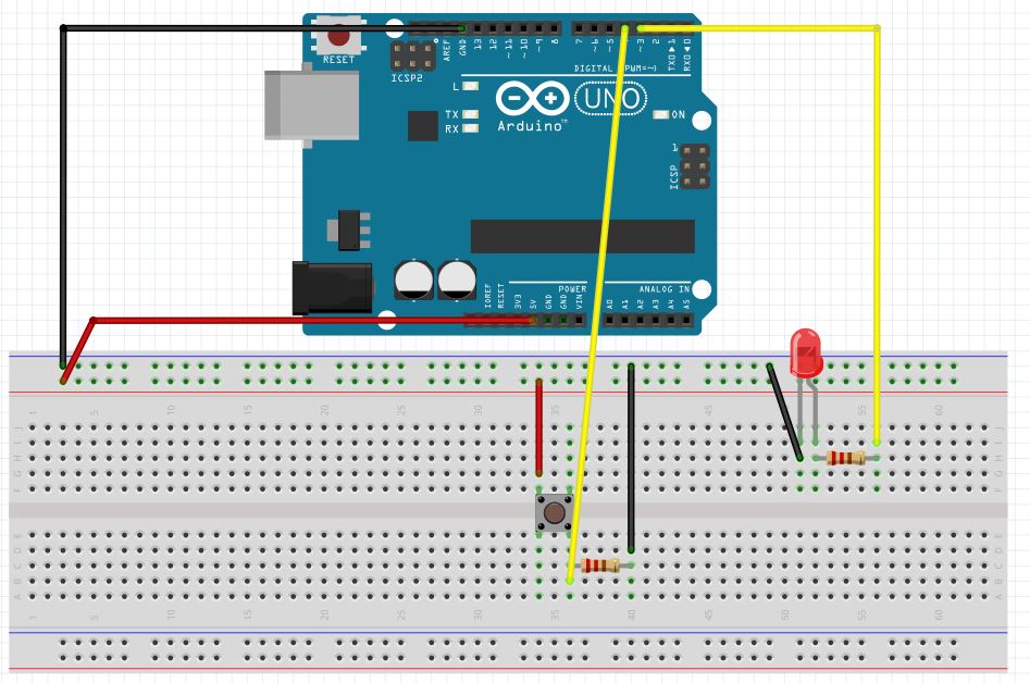 From that we can extract a couple of useful things that will be common along the course. Note that on the first two tracks we have black and red cables that go there from GND and 5V pins. Each project has to be powered and well you know that what we are building is a circuit one common practice with protoboard is using the first two tracks for power and ground so if a component of our circuit needs to grab them we can just use whatever pin of those two tracks and plug from there, it makes all the sense right? The other thing you may have noticed is that both the button and the led have a resistence between them and the rest of the circuit, that is because those two components do not have an inner resistence (or one big enough) and if being plugged without any external added resistance will probably get burned or harm the circuit.
Said that, You should already know that a button is a component that just lets the electrons flow when pressed and led is short for light emiting diode In here it is specially important to know that the larger stick is the anode and the shorter the catode, in a common led the current flows from the anode to the catode only and the resistence is serial connected to it in cases such as this one as in this example arduino provides 5V and a common led works at 2-3V (so we need to lower the V with a resistor).
Finally we see a couple of yellow cables that go from our components straight to the boards digital pwm pins. Those digital pins we have there, can be configured as input or output. In the case of the led, the pin number 10 will be configured as output and its values will be HIGHH or LOW, then HIGH that pin on the board will provide a power of 5V, when low no V will be provided, with that we are able to turn our led on or off. Same thing with the button, it will be configured as INPUT, with the “off” status when not pressed, as when not pressed the pin will go directly to ground (through the resistor) and when pressed the current will have the option to go to ground through the resistence or to go straight to the pin with no resistance and full V, you should already know what it’ll do.
Then the code for this example is the one that follows
int LED = 10;
int BUTTON = 4;
int val;

void setup() {
  pinMode(LED, OUTPUT);
  pinMode(BUTTON, INPUT);
}

void loop() {
   val = digitalRead(BUTTON);
   if(val==HIGH){
      digitalWrite(LED,HIGH);
   }
   else{
      digitalWrite(LED,LOW);
   }
}
There is no mistery with this code. Just note that in every simple program like this, we always have 3 parts. First we declare variables, then we run the setup function where we define all the pins we are using and their operational modes. Then we run the loop part. The code inside the loop part will be ALWAYS running in a while(true) cycle, that is important! Nothing more to comment on this one, just note that HIGH and LOW values are already built on the arduino (like a sort of global macros).
Led fading through pwm
Done that, we can run the extra mile with the following example, the following circuit should not requiere much explaination to you:
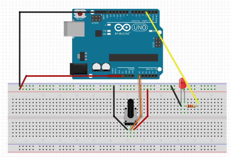 The general scheme is pretty similar to the other one. In this case we are using a (10kohm) potentiometer to set the “luminosity” of the led. We connect the potentiometer to the A0 (analogue!) port and the led to the 3 digital pin.
int LED = 3;
int POT = 0; //potentiometer
int LEDSHINE;

void setup() {
  // analog inputs do not requiere initialization
  pinMode(LED, OUTPUT);
}

void loop() {
  //analog read reads from 0 a 1023 in this case
   LEDSHINE = analogRead(POT)/4; //to adjust it to 255 scale
   analogWrite(LED, LEDSHINE);
}
The code is pretty interesting if you compared to the previous one. You should have noticed that no input pin is declared here. That is because analog inputs do not requiere initialization at all, arduino just reads whatever is sent there, no 0V OR 5V values, that makes sense because with analogue ports we want to retrieve values between a RANGE. So basically our analog port reads values from 0 a to 1023 “more info on analog inputs here!” and the led works in a 0-255 scale, so we do the conversion and thats it! Regarding to the led, a led is “RGB” and if you are familiar with that each RED, GREEN or BLUE works with a brightness level that goes from 0 to 255, voilà!
Just keep in touch and we’ll be back with the next one very soon! :)

Embedded systems programming with atmel328 - 2 (ultrasounds)
Madrid real estate renting market data analysis
